Developed Solidworks Design
Handle
When designing the new razor design I took to previous handle design and began by looking at how I could improve this. One area I found need addressing was the neck of the razor. Here it was rather low and didn’t have much curve. When considering ergonomics and comfort, I feel this wouldn’t be that comfortable to use so decided to address this issue first.
When addressing this issue I simply took the same razor design and adjusted the measurements of the different sketches around the neck of the razor. This allowed me to adjust the curve of the neck, improving the ergonomics and comfort of the razor.
After I adjusted the measurements around the neck area, I decided to change the shape of the handle itself. The previous design had a rounded bottom, and after further consideration I thought that by making the bottom of the handle concave it would increase the grip without the need of adding further rubber grips, ultimately reducing the overall cost of the product.
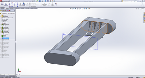
After this adjustment I was pleased with the appearance of the handle. I was then confident to go on and add further detail such as round off the bottom edge of the razor to make it more comfortable by using the revolve feature.
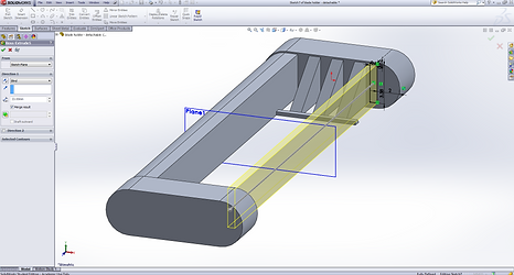
At this stage the handle was basically complete. I did however add further detail by adding a company logo to the handle, this was achieved firstly by deciding where I wanted to place the logo, then using sketch tools and the extrude feature, create the space for this logo to go.
I then used the Text tool to add the logo to the razor and then extruded the text so it would appear 3D when the razor was finished.
I also added a slot to the front of the razor, this would allow the small sphere to be attached which would allow the razor blades to be removed and replaced.
After the handle was complete and I was happy, I added some colour to the design to improve the appearance and allow for more photo realistic render to be created.
GRIP
After the handle design was complete, it was time to consider the ergonomics and comfort of the product. To do this I looked at adding various grips to the design, similar to that of the initial design.
However I wasn’t pleased with this method, and found that it looked strange. To address this I decided to produce a sketch of a design I had in mind and begin to create this on Solidworks. My thoughts behind this where to have a single grip that extended down the side of the razor handle, providing grip not only where the fingers will be placed along the top of the razor, but along the sides, providing more grip when adjusting the razor / changing hand positions when it is wet.
To create this I firstly began by drawing a rough shape using the various sketch tools and extruded this to the length I desired. I ensured that the sketch was the same width as the handle of the razor to ensure a good fit when it came to mating the parts together.
After the shape was extruded, I the selected the right plane and began to draw the shape of the grip I had designed. This was a simple straight section at the top that would be placed on top of the handle, and the remainder of the grip was along the side of the handle.
The shape was drawn and extrude cut, in order to successfully extrude cut the piece, I had to ‘flip side to cut’ so that the feature would not cut the inside of the drawing as usual, but anything outside of it, leaving the profile I had drawn.
I began to then add some aesthetic qualities to the grip by rounding over the top end of the grip, providing a more pleasing to look at part as well as a more comfort.
At this stage in was very happy with the design; however I thought that by adding two slots along the top face of the grip would provide the user with some extra grip. This would allow for the water to be removed effectively, ensuring the grip is kept clear from water, providing the ultimate griping surface for the user, reducing the risk of the product slipping.
Sphere Connector
This sphere connector was created in order to allow for the user to remove the razor blades for replacement. The connector works but locking into the razor head and is removed by simply pressing down on the sphere, releasing the razor head.
The design was firstly created by drawing out a simple 3D rectangle that was the same dimensions as the slot cut in the front of the razor, but slightly longer, protruding over the edge of the razor handle slightly.
A plane was then created to sit in the middle of the rectangle, and using the various sketch tools I drew the sphere shape with the angled top to allow for the user to comfortably press down on the sphere. To create the sphere this was achieved by using the revolve feature.
After this was complete the sphere connector was finished and various colours were added, keeping with the colour scheme at the time. I also added a rubber grip appearance to the angled top of the sphere as there is a possibility that this will be sued by the user whilst the product is wet.
Razor head
The next stage of the Solidworks design process was to create the razor head that would attach to the main handle of the body and allow for the razor blade holder to pivot.
To begin creating this part I started off by simple drawing a eclipse that would be the main body of this part. The sketch was then extruded using the extrude feature.
I then added some design to the part, looking to create a more streamlined design, taking inspiration from the biomimicry study I carried out at the very start.
I added a sketch to the front face of the previously extruded body and extruded this to create the more streamlined and aesthetically pleasing part.
I then added further design to the previously drawn part by drawing another eclipse, by instead of simply extrude cutting this, I flipped the side to cut, so the feature would cut the outside of the eclipse and not the material on the inside. This produced a complex but good looking shape.
To allow for the blade holder to attach and pivot I had to create arms that extended either side of the part that could then attach to the razor blade holder. This was achieved by simply drawing a shape on the mid plane and the extruding this evenly.
Further design and refinement was done in order to make the part more aesthetically pleasing. I added some curves to the back side of the part to simply add to the parts complexity. This was achieved through creating the curves through sketching and then extrude cutting the drawing.
Again going back to the arms that will hold the razor blade holder, I added some further material that will be used to create this attachment. A drew a simple square using the sketch tools and extruded it along the front face, giving me some material to work with in regards to creating the attachment for the razor blade holder.
After the square was extruded this allowed me to then view onto the front of the extruded square, and draw a large rectangle. This rectangle would then be extruded to the desired length, providing me with the material to cut away to create the attachment arms for the razor blade holder.
Now that I had material to work with, I selected the top plane and began to create the desired shape for the arms. This was achieved by using the sketch tools to create the initial shape and then the extrude cut feature to remove the wastage. After the waste was removed, this left me with the basic shape for the razor blade holder to attach to.
I decided to add a slight instep where the previous shape was cut. This not only added to the aesthetic qualities of the part, but created a less ‘chunky’ design, making the design of the product feel more considered and complex.
Next I added the slot at the back of the razor head that would allow the ball connector to connect to. This was created by simply taking the same measurements used to create the ball connector and using this to create the slot, extrude cutting it to the correct depth.
Lastly the pivot point for the razor blade holder to connect to was added. This was created by simply drawing and extruding a simple circle at the end of one of the arms. I then mirrored this part to the other side of the part, preventing me from having to redraw and position the circle accurately.


Razor Blade Holder
When designing the razor blade holder I took various steps when designing it through sketching, beginning with a basic sketch and developing it until I was happy with the design. Once happy I began to create this part on solidworks by firstly drawing the overall shape using the straight slot sketch tool.
I used this tool and extruded it to 40mm, giving me to correct length and adequate size to work with in regards to removing material and shapig it to the desired shape.
Next I created an instep on the inside of the extruded shape. I simply drew a centre rectangle on a plane I had created which was positioned in the centre of the extruded shape. I then extrude cut the centre rectangle to 33mm, leaving me with two sides that will allow for further detail to be added between them to allow for the secure holding of the razor blads.
After the two sides where created I then went ahead and began constructing the supports for the blade holder. These supports where created by drawing a semi-cirle that was aliglhty smaller in size in regards to the dimension of the exteruded slot. I then extruded this shape so that it would ac as a support for the two sides.
After the support was added I began to create the slots where the blades will be held. To do this I created an angled section on the side of the part, which will later have the slots added. To create this angled side I simply selected the area I wanted to draw on, in this case it was the right plane, and then used the sketch tools to create the angled shape.
To create the slots for the blades to fit into, I simply selected the angle face as the area to draw on, and drew 4 rectangles which were evenly spaced apart. These rectangles would then be extruding cut in order to create the slots for the blades to fit into.
I noticed that after I had made the cut, it didn’t look as good as I expected. So to address this issue and tidy the cut up I simply traced around the first initial extruded slot and extruded it again, but this time only making it a few MM’s, tidying up this area.
After the first side was complete and I was happy, I decided that to save time and ensure accuracy I could simply mirror the features over to the other side. To do this I selected the various parts I had drawn and extruded / extrude cut and mirrored them from the mid-plane I had inserted towards the beginning when creating this part.
This allowed me to mirror the features over to the other side, ensuring they were accurately placed and would align.
Next I began to create the support for the back of the razor blade holder. I drew a rectangle on the side of the first extruded part ensuring it lined up with the slots cut that hold the razor blades. This was then extruded across the length of the razor blade holder, creating the first initial support for the back of the razor blade holder.
Next I added a section below this extruded support in the same way, by using the sketch feature and also extruding it the whole way across the part. This was added to allow for the moisturising strip to be placed below it, ensuring it is placed before the blades, so that the skin is moisturised before shaving.
This feature was then filleted to make it appear more aesthetically pleasing and also remove any sharp edges as this will come in direct contact with the users’ skin.
I then added the area where the moisturising strip would later be added. Again this was created by drawing the shape using the sketch tools and then extruding it.
In order for the moisturising strip to be added, I drew a slightly smaller inner rectangle inside the previously extruded shape. This smaller rectangle was then extrude cut, allowing for the moisturising strip to be created and added later. This extrude cut would also ensure that the first part touching the users skin would be the moisturising strip as the sharp edge was removed (see screenshot below).
Next further support was added, increasing the parts stability. This again was created through the use of sketch tools as well as the extrude feature.
Next the hole was then added. This hole would allow for the razor blade holder to be fixed to the razor head. The hole would also allow the razor blade holder to pivot and move, following the contours of the human body and face.
To improve the functionality of the art and make the shaving process more comfortable, a slot was cut out along the front edge of the part and patterned across, creating a line of multiple slots. These slots would allow for further moisturising gel to be added, increasing the functionality of the product by providing a smoother more comfortable shave, especially for those who have sensitive skin.
It was at this stage I decided it may be useful to add another moisturising strip to the front of the razor blade holder. This again would provide more comfort when the user is shaving. To do this I simply mirrored the first moisturising strip created earlier across to the front of the part. This was quick and easy and as the part had been created to strict dimensions, ensuring that the mirror feature would place the part exactly where needed.
At this stage I decided to add the moisturising strips into the pre-cut slots. This was merely for visual representation to show how the feature would work / function when the final design is to be rendered.


Razor Blades
The final part to create was the razor blades. I needed to ensure the razor blades fitted into the slots I had cut in the razor blade holder. So I simply took the dimensions from the slots and used these in the creation of the blades.
When creating the razor blades I firstly drew out a construction box to the dimension required.
I then drew the initial shape inside this box, adding a slight overhang at the bottom; this would be the blade itself.
After this was drawn I simply extruded the shape to the correct width.


